2019年8月13日星期二


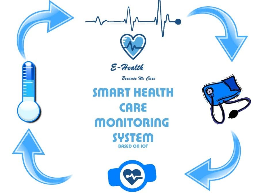
Smart Health Care Monitoring System Based on IoT
This project includes hardware which will measure blood pressure, heart rate, ECG & temperature, and send to Android application & Firebase.
Things used in this project
Hardware components
Arduino UNO & Genuino UNO ×1
HC-05 Bluetooth Module ×1 SparkFun Single Lead Heart Rate Monitor - AD8232 ×1 DFRobot Gravity: Analog LM35 Temperature Sensor For Arduino ×1 ProtoCentral Pulse Oximeter & Heart Rate Sensor based on MAX30100 ×1 Breadboard (generic) ×1 Sunrom Blood Preasure Module ×1 On Semiconductor EU-SIGFOX-GEVB ×1
Software apps and online services
Android Studio
Arduino IDE
Google Firebase
Hand tools and fabrication machines
10 Pc. Jumper Wire Kit, 5 cm Long
Story
Introduction
This project is significant in various ways because in today's world, everyday many lives are affected because the patients are not timely and properly operated. Also for real time parameter values are not efficiently measured in clinic as well as in hospitals.Sometimes it becomes difficult for hospitals to frequently check patient’s conditions. Also continuous monitoring of ICU patients is very difficult. To deal with these types of situations, our system is beneficial. Our system is designed to be used in hospitals and homes also for measuring and monitoring various parameters like temperature, ECG, heart rate, blood pressure. The results can be recorded using Arduino. Also the doctors can see those results on android app. The system will also generate an alert notification which will be sent to doctor. Our system is useful for monitoring health system of every person through easily attach the device and record it. In which we can analysis patient’s condition through their past data, we will recommend medicines if any emergency occurred through symbolic A.I.
Work Flow:
First of all we have to make Communication between Arduino and android app using Bluetooth. for the android code for this communication kindly follow the link below
https://solderer.tv/data-transfer-between-android-and-arduino-via-bluetooth/
now after establishing the communication successfully start creating android app using android studio and use the code from above link after this send some data to arduino in our scenario we have 4 module so we have 16 combination like patient want only temperature data or ecg, Blood pressure or temperature and ecg etc. so for these 16 combination we use hexa table which stars from 0 and ends at 'F' so after reading the incoming value arduino decide which type of data user wants. After that arduino start reading that data from sensors and transfer that data to arduino using HC05 and android receive that data and send to firebase which is real time database below is the structure of firebase database


this is the complete architecture of our project.
Circuit Picture:


I hope you enjoy this project
Schematics
Block Diagram
Click here to Download

Code
Arduino Code (Arduino)#define USE_ARDUINO_INTERRUPTS true
#include <PulseSensorPlayground.h>
#include <SoftwareSerial.h>
SoftwareSerial mySerial(10, 11); // RX, TX
const int PulseWire = 0;
int tempPin = 1;
int ECGPin = 2;
String incomingByte;
int value;
int myBPM =0;
int finalBPM ;
float volts=0.0;
float cel =0;
String stringTemp;
String stringBPM;
bool is_data_send=false;
bool ISBP=false;
bool ISECG=false;
bool ISHR=false;
bool IStemp=false;
const int LED13 = 13;
int Threshold = 550;
String data="";
PulseSensorPlayground pulseSensor;
void setup() {
Serial.begin(38400);
Serial.println("Enter AT commands:");
mySerial.begin(38400);
pulseSensor.analogInput(PulseWire);
pulseSensor.blinkOnPulse(LED13);
pulseSensor.setThreshold(Threshold);
if (pulseSensor.begin()) {
Serial.println("We created a pulseSensor Object !");
}
}
void loop() {
if (mySerial.available()) {
incomingByte = mySerial.read();
Serial.println(incomingByte);
if(incomingByte=="49")
{ISECG=false;ISBP=false;ISHR=false;IStemp=true;is_data_send=true;}
else if(incomingByte=="50")
{ISECG=false;ISBP=false;ISHR=true;IStemp=false;is_data_send=true;}
else if(incomingByte=="51")
{ISECG=false;ISBP=false;ISHR=true;IStemp=true;is_data_send=true;}
else if(incomingByte=="52")
{ISECG=false;ISBP=true;ISHR=false;IStemp=false;is_data_send=true;}
else if(incomingByte=="53")
{ISECG=false;ISBP=true;ISHR=false;IStemp=true;is_data_send=true;}
else if(incomingByte=="54")
{ISECG=false;ISBP=true;ISHR=true;IStemp=false;is_data_send=true;}
else if(incomingByte=="55")
{ISECG=false;ISBP=true;ISHR=true;IStemp=true;is_data_send=true;}
else if(incomingByte=="56")
{ISECG=true;ISBP=false;ISHR=false;IStemp=false;is_data_send=true;}
else if(incomingByte=="57")
{ISECG=true;ISBP=false;ISHR=false;IStemp=true;is_data_send=true;}
else if(incomingByte=="65")
{ISECG=true;ISBP=false;ISHR=true;IStemp=false;is_data_send=true;}
else if(incomingByte=="66")
{ISECG=true;ISBP=false;ISHR=true;IStemp=true;is_data_send=true;}
else if(incomingByte=="67")
{ISECG=true;ISBP=true;ISHR=false;IStemp=false;is_data_send=true;}
else if(incomingByte=="68")
{ISECG=true;ISBP=true;ISHR=false;IStemp=true;is_data_send=true;}
else if(incomingByte=="69")
{ISECG=true;ISBP=true;ISHR=true;IStemp=false;is_data_send=true;}
else if(incomingByte=="70")
{ISECG=true;ISBP=true;ISHR=true;IStemp=true;is_data_send=true;}
}
//Getting Values from Sensors
if(is_data_send)
{
int counter=0;
if(IStemp||ISHR){
while(counter<10){
if(IStemp){
value=analogRead(tempPin);
volts=(value/1024.0)*5.0; //conversion to volts
cel = cel+(volts*100.0);
}
if(ISHR){
if (pulseSensor.sawStartOfBeat()) {
myBPM = myBPM+pulseSensor.getBeatsPerMinute();
}
}
counter=counter+1;
}}
if(ISBP){
}
int counter2=0;
if(ISECG){
while(counter2<500){
if((digitalRead(2)==1)||(digitalRead(3)==1)){}
else{
String abc=String(analogRead(ECGPin));
Serial.println(abc);
data+=abc+"|";
}
counter2=counter2+1;
}
}
}
//Sending Data
if(is_data_send){
if(ISBP){
}
if(ISHR){
float final_bpm=myBPM/10;
stringBPM = String(final_bpm);
data+=stringBPM+"|";
}
if(IStemp){
float final_temp=cel/10;
stringTemp = String(final_temp);
data+=stringTemp+"|";
}
Serial.print("Data sending");
Serial.print(data);
//Serial.print(stringTemp+"|"+stringBPM);
mySerial.print(data);
mySerial.println();
is_data_send=false;
}
delay(20); // considered best practice in a simple sketch.
}
This article copied from hackster.io, Author: Abdullah Mukhtar, Muneeb Abdul Rauf
2019年8月11日星期日
Introduction & Playing of micro: Maqueen
The link of micro: Maqueen micro:bit Educational Programming Robot Platform:
https://www.dfrobot.com/product-1783.html
We also have many micro: Maqueen kits!
Introduction
Best DIY Robot kit for beginners - Micro:Bit
DFRobot micro Maqueen Motor and Line Sensor
Amazing! DIY Robot kit Maqueen V2.0 - BBC Micro:Bit
Amazing DIY Robot Kit
Maqueen micro:bit Educational Programming Robot Platform
Playing with the BBC Micro:Bit robot
DIY Cheap Education Robot with $20
Plataforma Robot de Programación Educativa
micro-bit robot multipurpose MAQUEEN programmed with scratch perfect for CHILDREN
Micro: bit robot project - How to make a Snake Robot
Smartphone controlled Robot
Como programar y armar robot Maqueen con control remoto x infrarrojo con arduini mini por DFRobot
The STEM Robot for Kids: Maqueen Runs The Egg
Personal Lightning Detector
Build your own lightning detector that's smaller, more customizable, and cheaper than a commercial one!

Things used in this project
Hardware components
DFRobot Beetle - The Smallest Arduino ×1
DFRobot Lightning Sensor ×1
DFRobot LiPoly Charger ×1
Small Piezo Buzzer ×1
500 mAh Lipoly ×1
Slide Switch ×1
Hand tools and fabrication machines
Soldering iron (generic)
Hot glue gun (generic)
Wire Strippers (generic)
Story
In this project, we'll create a small device that alerts you to nearby lightning strikes. The total cost of all materials in this project will be cheaper than purchasing a commercial lightning detector, and you'll get to hone your circuit-making skills in the process!
The sensor used in this project can detect lightning strikes up to 40 km away, and is also capable of determining the distance of a strike to within a tolerance of 4 km. While this is a reliable sensor, you should never depend upon it to warn you of lightning strikes if you're outdoors. Your own circuit handiwork will not be as reliable as a commercial lightning detector.
This project is based upon the AS3935 lightning sensor IC, with a carrier circuit from DFRobot. It detects electromagnetic radiation that's characteristic of lightning and uses a special algorithm to convert this information to a distance measurement.
Supplies:
This project only requires a few parts. Information is outputted to the user via a piezo buzzer, and the circuit is powered through a lithium ion polymer battery. Below is a complete list of all the parts:
DFRobot Lightning Sensor
DFRobot Beetle
DFRobot LiPoly Charger
Piezo buzzer (only need one - many different types work)
500 mAh LiPoly (any 3.7V LiPoly will work)
Slide switch (any small switch will work)
In addition to these items, you'll want the following tools/items:
Soldering iron
Solder
Hookup wire
Wire strippers
Hot glue gun
I also detail the process of creating a 3D-printed case for this project. If you don't have a 3D printer, operating the device without a case is still fine.
Step 1: The Circuit
 As there's a relatively small number of parts in this build, the circuit is not particularly intricate. The only data lines are the SCL and SDA lines for the lightning sensor and one connection for the buzzer. The device is powered by a lithium ion polymer battery, so I decided to also integrate a lipoly charger into the circuit.
The above image depicts the entire circuit. Note that the connection between the lipoly battery and the lipoly battery charger is via the JST male/female connectors and does not require soldering. See the video at the beginning of this project for further details on the circuit.
Step 2: Circuit Assembly
 Final Circuit Before Folding

Final Circuit After Folding
This device is a great candidate for a circuit assembly technique known as free-forming. Rather than affix the parts in this project to a substrate such as a perf board, we will instead just connect everything with wires. This makes the project much smaller, and it is somewhat faster to assemble, but generally produces less aesthetically pleasing results. I like to cover my free-formed circuits with a 3D-printed case at the end. The video at the beginning of this project details the free-forming process, but I will go over all the steps I took textually as well.
First Steps
The first thing I did was unsolder the green terminal blocks from the lipoly charger. These aren't needed, and take up space. I then connected the "+" and "-" terminals of the lipoly charger to the "+" and "-" terminals at the front of the Beetle. This feeds the raw voltage of the lipoly battery straight into the microcontroller. The Beetle technically needs 5V, but it will still operate on the roughly 4V from the lipoly.
Wiring the Lightning Sensor
I then cut the included 4-pin cable such that roughly two inches of wire remained. I stripped the ends, plugged the cable into the lightning sensor, and made the following connections:
"+" on the lightning sensor to "+" on the Beetle
"-" on the lightning sensor to "-" on the Beetle
"C" on the lightning sensor to the "SCL" pad on the Beetle
"D" on the lightning sensor to the "SDA" pad on the Beetle
I also connected the IRQ pin on the lightning sensor to the RX pad on the Beetle. This connection needed to go to a hardware interrupt on the Beetle, and the RX pad (pin 0) was the only interrupt-capable pin remaining.
Wiring the Buzzer
I connected the short lead of the buzzer to the "-" terminal on the Beetle (ground), and the long lead to pin 11. The buzzer's signal pin should be connected to a PWM pin for maximum versatility, which pin 11 is.
Switching the Battery
The last thing necessary is to add a switch inline to the battery to turn the project on and off. To do this, I first soldered two wires to adjacent terminals on the switch. I fixed these in place with hot glue, as the switch's connections are fragile. I then cut the red wire on the battery about halfway down, and soldered the wires coming off the switch to each end. Make sure you cover the exposed sections of wire with heat shrink tubing or hot glue, as these could easily come in contact with one of the ground wires and make a short. After adding the switch, you can plug the battery into the battery charger.
Folding Everything In
The last step is to take the gangly mess of wires and components and make it look somewhat presentable. This is a delicate task, as you want to be sure that you don't break any wires. I first started by hot gluing the lipoly charger to the top of the lipoly battery. I then glued the Beetle on top of that, and finally glued the lightning sensor at the very top. I left the buzzer to sit off to the side, as shown in the above image. The final result is a stack of boards with wires running throughout. I also left the switch's leads to run freely, as I later wish to integrate those into a 3D-printed case.
Step 3: Programming
The software for this circuit is simple at the moment but is heavily customizable to suit your needs. You can find it in the "code" section. When the device detects lightning, it will first beep many times to alert you that lightning is nearby, then beep a certain number of times corresponding to the lightning's distance. If the lightning is less than 10 kilometers away, the device will emit one long beep. If it is more than 10 km from you, the device will divide the distance by ten, round it, and beep that many times. For example, if lightning strikes 26 km away, the device will beep three times.
The entire software revolves around interrupts from the lightning sensor. When an event is detected the lightning sensor will send the IRQ pin high, which triggers an interrupt in the microcontroller. The sensor can also send interrupts for non-lightning events, such as if the noise level is too high. If the interference/noise is too high, you'll need to move the device away from any electronics. The electromagnetic radiation coming from these devices can easily dwarf the comparatively weak electromagnetic radiation from a distant lightning strike.
To program the microcontroller you can utilize the Arduino IDE - make sure the board selection is set to "Leonardo." You will also need to download and install the library for the lightning sensor. You can find this here.
Step 4: 3D-Printed Case
 Case Rendered in Carbon Fiber
 Case Rendered in ABS
I modeled a case for my device. Your free-form circuit will likely have different dimensions, but I tried to make my case big enough such that many different designs can still fit in it. You can download the files here, and then print them out. The top of the case snaps on to the bottom, so no special parts are required for the case.
You can also try making a model of your own device and creating a case for it. I detail this process in the video at the beginning of this project, but the basic steps to follow are as such:
Capture the dimensions of your device
Model your device in a CAD program (I like Fusion 360 - students can get it for free)
Create a case by offsetting a profile from the device model. A tolerance of 2 mm generally works well.
Step 5: Using Your Device and More
Congratulations, you should now have a fully-functioning lightning detector! Before using the device for real, I recommend waiting until there's a thunderstorm around you to make sure that the device actually is capable of detecting lightning. Mine worked the first try, but I do not know the reliability of this sensor.
Charging the device is simple - you can just plug a micro-USB cable into the lipoly charger until the charging light turns green. Make sure that the device is on while you charge it, or no power will go to the battery! I also recommend changing the beeps to something that you like more; you can use the Tone.h library to generate more pleasant-sounding notes.
Let me know in the comments if you have any problems or questions. To see more of my projects, check out my website www.AlexWulff.com.
Custom parts and enclosures
CaseTop Click Here to Download
CaseBottom Click Here to Download
Schematics
Device Circuit

Code
Lightning (Arduino)/*
* Original Sketch from DFRobot.com
* Modified by Alex Wulff (www.AlexWulff.com)
* on 7/25/19
*/
#include "Lib_I2C.h"
#include "DFRobot_AS3935_I2C.h"
#define AS3935_CAPACITANCE 96
// Indoor/outdoor mode selection
#define AS3935_INDOORS 0
#define AS3935_OUTDOORS 1
#define AS3935_MODE AS3935_INDOORS
// Enable/disable disturber detection
#define AS3935_DIST_DIS 0
#define AS3935_DIST_EN 1
#define AS3935_DIST AS3935_DIST_EN
// I2C address
#define AS3935_I2C_ADDR AS3935_ADD3
#define IRQ_PIN 0
#define BUZZ 11
#define LIGHT 13
void AS3935_ISR();
DFRobot_AS3935_I2C lightning0((uint8_t)IRQ_PIN, (uint8_t)AS3935_I2C_ADDR);
// Needs to be voltatile because this variable is accessed in an ISR
volatile int8_t AS3935_ISR_Trig = 0;
void setup()
{
Serial.begin(115200);
Serial.println("Lightning Sensor Start");
I2c.begin();
I2c.pullup(true);
I2c.setSpeed(1);
delay(2);
lightning0.defInit();
lightning0.manualCal(AS3935_CAPACITANCE, AS3935_MODE, AS3935_DIST);
attachInterrupt(digitalPinToInterrupt(IRQ_PIN), AS3935_ISR, RISING);
pinMode(BUZZ, OUTPUT);
pinMode(LIGHT, OUTPUT);
}
void loop()
{
// blink light while waiting for lightning
while (AS3935_ISR_Trig == 0) {
digitalWrite(13, HIGH);
delay(700);
digitalWrite(13, LOW);
delay(200);
}
delay(5);
// Reset interrupt flag variable
AS3935_ISR_Trig = 0;
// Get interrupt source
uint8_t int_src = lightning0.getInterruptSrc();
// lightning nearby
if (int_src == 1) {
uint8_t lightning_dist_km = lightning0.getLightningDistKm();
if (lightning_dist_km == 1) {
Serial.println("Lightning overhead!");
}
else if ((lightning_dist_km >= 5) && (lightning_dist_km <= 40)) {
Serial.println("Lightning occurs!");
Serial.print("Distance: ");
Serial.print(lightning_dist_km);
Serial.println(" km");
}
else if (lightning_dist_km == 0x3F){
Serial.println("Out of range.");
}
// Get lightning energy intensity
uint32_t lightning_energy_val = lightning0.getStrikeEnergyRaw();
Serial.print("Intensity: ");
Serial.print(lightning_energy_val);
Serial.println("");
// round to nearest tens place
float distf = (float)lightning_dist_km;
int dist_tens = (int)roundf(distf / 10);
// buzz to get attention
for (int i = 0; i < 20; i++) {
digitalWrite(BUZZ, HIGH);
delay(25);
digitalWrite(BUZZ, LOW);
delay(25);
}
if (lightning_dist_km <= 5) {dist_tens = 1;}
// buzz to indicate distance
for (int i = 0; i < dist_tens; i++) {
digitalWrite(BUZZ, HIGH);
delay(1000);
digitalWrite(BUZZ, LOW);
delay(1000);
}
}
// interference detected
else if (int_src == 2)
{
for (int i = 0; i < 3; i++) {
digitalWrite(LIGHT, HIGH);
delay(200);
digitalWrite(LIGHT, LOW);
delay(200);
}
Serial.println("interference detected");
}
// too much noise
else if (int_src == 3)
{
for (int i = 0; i < 5; i++) {
digitalWrite(LIGHT, HIGH);
delay(100);
digitalWrite(LIGHT, LOW);
delay(100);
}
Serial.println("Noise level too high!");
}
}
//ISR function just sets the flag to 1
void AS3935_ISR()
{
AS3935_ISR_Trig = 1;
}
2019年8月6日星期二
How to Make a Gaming Tablet with Lattepanda at home
Hello, Friend. In this video I will show you How to Make a Gaming Tablet Using Lattepanda 4GB/64GB board and its Windows10 Developer board but its look like Very mini board but its powerful Operating system of this mini Computer is running windows 10 pre- installed board. I made its body from cheapest acyclic sheet and I have using 7 inches Touch IPS Display and I made this Gaming Tablet. I Hope you will enjoy this video.
Required Material-
LattePanda V1.0 - A Powerful Windows 10 Mini PC 4GB/64GB
You can also use LattePanda V1.0 - A Powerful Windows 10 Mini PC 2GB/32GB
7" Capacitive Touch Panel Overlay for LattePanda V1.0 IPS Display
7" 1024 x 600 IPS Display for LattePanda V1.0
Mobile Controlled ESP32 Two-Wheel Drive Robot
This project shows you how to make a smartphone-controlled robot using ESP32.

Things used in this project
Hardware components
DFRobot FireBeetle ESP32 IOT Microcontroller (Supports Wi-Fi & Bluetooth) ×1
DC motor (generic) ×2
Analog Comparator, w/ Voltage Ref ×1
DC Motor Driver, Full Bridge ×1
Breadboard (generic) ×1
Wheels ×2
Jumper wires (generic) ×1
Software apps and online services
STEMpedia Dabble
STEMpedia Pictoblox
Story
Today’s project is not going to be based on evive. Today, we’re going to make yet another smartphone-controlled robot but this time using ESP32. It can move forward, back, right, left, and doesn’t need Bluetooth! We’re to program it in PictoBlox, our graphical programming software with advanced interaction capabilities and control it using Dabble, our smart project interaction and controller app.
You can download PictoBlox from HERE and get Dabble on Google Play.
Ready to make the robot?
Let’s begin!
Step 1: List of Components Required
Hardware
ESP32
Motor Driver
Dual Shaft BO Motor
BO Motor Mount
BO Wheel
Caster Wheel
Breadboard
Samsung 3.7V 2600 mAh Lithium-Ion Battery
Acrylic Base Plate
Standoffs
Jumper Cable
Nuts and Bolts
Software
PictoBlox
Dabble
Step 2: Assembly of the 2-Wheel Drive Robot
Attach the motor mounting brackets to the bottom of the chassis using M3 bolts of 8mm length and M3 nuts.

Attach the two Dual Shaft BO motors to the motor brackets on the chassis using M3 bolts of 25mm length and M3 nuts.

Note: Make sure that the motor's wires are faced forward and are inwards.
Next, fit the wheels into the motor shafts.


As ESP32 has no internal battery, we need to supply external power to it. Thus, to hold up the external battery, we need to attach the 3D printed battery holder using M3 nuts and bolts.

As we already know, that for a 2-wheel drive robot we need third support which is the Caster wheel.
Mount three M3 standoffs on the caster wheel. Fasten the caster wheel with the standoffs to the chassis using M3 bolts of 8mm length.

Finally, flip the entire assembly.
Step 3: Connecting ESP32
Connect the ESP32 board, Voltage Regulator and Motor Driver on the Breadboard:

Make the connections as listed below:
Connect battery +ve terminal to the input of 7805 voltage regulator IC and” VIN” of Motor driver IC
Connect its -ve terminal to “GND” of ESP32 Dev Board, ” GND” of Motor Driver IC, “GND “of the Voltage regulator IC ( 7805)
Connect OutPut of voltage regulator IC to” VIN” of ESP32 Dev Board and “VCC” of Motor Driver IC
Connect Motor1 Enable Pin i.e EN1 present on the motor driver IC to pin D14 present on the ESP32 Dev Board. similarly, Connect EN2 to pin D23 of the ESP32 Dev Board
Connect Motor 1 Direction Control Inputs pin (i.e Pin IN A1 and IN A2) to D12 and D13 pin present on the ESP32 Dev Board Respectively.
Connect Motor 2 Direction Control Input pin (i.e Pin IN B1 and IN B2) to D22 and D23 respectively.
Connect one end of motor 1 to OUT A1 and another end to OUT A2.similarly, Connect one end of motor 2 to OUT B1 and another end to OUT B2

Step 4: Complete the Assembly
Once have made the two-wheel drive and the connections, fix the breadboard on your two-wheel robot above the chassis using a Double-sided tape.
Finally, connect a 7.4V Lithium Polymer Battery to ESP32.
Your robot is thus complete.

Step 5: Working of the Robot
We will be controlling the Smartphone using Dabble. Install Dabble and open it on your Smartphone.
Connect the Dabble by clicking on the Connect-Disconnect button and selecting your device's name from the menu. Open Gamepad and there you go!
The robot takes actions according to the button pressed. For example,
Up: Robot will move forward
Down: Robot will move backward
Left: Robot will turn left
Right: Robot will turn right
If none of the buttons is pressed, the robot will stop.
Step 6: PictoBlox- Graphical Code
Working with an ESP has never been this easy. Now just code it by dragging and dropping some blocks in PictoBlox.


You can download PictoBlox from here. Once installed, make the above script and upload it to your board.
Click Here to Download ESP32%2BMobile%2BRobot.sb3
Step 7: Arduino Code
You can also code it using Arduino:
Click Here to Download Mobile%2BControlled%2BESP32%2BRobot.ino
Step 8: Conclusion
With this, your robot is all set to do what you ask it to! ;)
Schematics
Fritzing Diagram for ESP32 robot Click Here to Download
Code
Click Here to Download Mobile+Controlled+ESP32+Robot.ino (Arduino)
Click Here to Download PictoBlox Code for ESP32 robot (Scratch)
Click Here to Download evive Library (C/C++)
Click Here to Download Dabble Library (C/C++)
This article copied from hackster.io, Author: STEMpedia
订阅:
博文 (Atom)