Things used in this project
Hardware components
Elegoo Arduino UNO R3
× 1
Elegoo RGB LED, 4-pin, diffused
× 1
Elegoo Resistor, 220 ohms, 1/4W, 1%
× 3
Breadboard (generic)
Breadboard (generic)
× 1
Elegoo DuPont connection wires, M-M
× 4
Software apps and online services
Software apps and online services
Arduino IDE
Story
Introduction
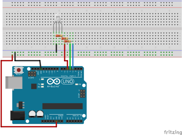
This technical note is an introductory exercise in evaluating the four-pin RGB LED (common anode) device. The key advantage of this device is that separate LEDs are not needed although a dedicated pin and resistor pair are needed for each RGB color index. The exercise is limited to iterating over the full color spectrum (i.e. 16 million RGB discrete values). Subsequent exercises will apply the features after integration with sensors that could benefit from visual non-textual display.
Goals and Objectives
The key objective of the exercises is to blink through the full RGB spectrum of the four-pin diffused RGB LED device.
The goal of the exercise is to establish and environment for rapid integration of visual cues to low cost sensors such as Passive Infra-Red motion and Ultrasonic distance.
Exercises
The exercise in this note leverages the ELEGOO UNO starter kit which contains the required hardware components. The primary exercises are to:
- Blink the primary colors (i.e. Red, Green and Blue)
- Blink key color indices (using a reference table)
- Blink through entire available color spectrum for device:
- 255 values for each primary color
- 16 million combinations
Display
The serial monitor display has been intentionally omitted from this exercise since the focus is on visual display of colors.
Pull-Up Resistor
The calculation of the values for the pull-up resistors will vary slightly for each primary color of the LED device. However, these differences in the nominal value are small (and the fact that no color calibration is intended in this note) enough to consider a single value for all three colors.

Summary
This primary purpose of this note is to ensure that the installed four-pin diffused LED device is displaying the full color RGB (one byte per primary color) spectrum. This solution will be integrated with other sensors in a future note where the primary emphasis will rely on visual feedback.
References
Custom parts and enclosures
Schematics
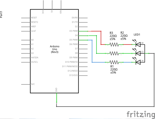
Schematic
Test schematic for 4-pin RGB LED
Code
ElegooRGBled-01.inoC/C++
Display discrete color spectrum using a single RGB 4-pin LED.
/*
 * ElegooRGBled-01.ino
 * Display discrete color spectrum using a single RGB 4-pin LED
 * adapted from examples at https://www.elegoo.com/
 * 2018-09-12
 * armw
 * v0.1
 * � 2018 <reza@parkcircus.org> All Rights Reserved
 *
 * This program is free software; you can redistribute it and/or modify
 * it under the terms of the GNU General Public License as published by
 * the Free Software Foundation; either version 2 of the License, or
 * (at your option) any later version.
 *
 * This program is distributed in the hope that it will be useful,
 * but WITHOUT ANY WARRANTY; without even the implied warranty of
 * MERCHANTABILITY or FITNESS FOR A PARTICULAR PURPOSE.  See the
 * GNU General Public License for more details.
 *
 * You should have received a copy of the GNU General Public License
 * along with this program; if not, write to the Free Software
 * Foundation, Inc., 51 Franklin Street, Fifth Floor, Boston,
 * MA 02110-1301, USA.
 *
 * Notes
 *   RGB LED:
 *     Pin #  Description
 *     1      Red display
 *     2      Common anode
 *     3      Green display
 *     4      Blue display
 *   Color wheel: https://en.wikipedia.org/wiki/RGB_color_model
 */

#define MAX_BITS    255           // number of bits in a byte
#define MAX_COLORS  16            // number of color codes defined in custom RGB table
#define MAX_LEDPINS 3             // number of leads in RGB LED assigned to display color

enum pins
{
  red = 0,
  green = 1,
  blue = 2
} rgbLED;

struct ColorWheel
{
  public:
    byte rgb[3];                  // RGB intensity values, scale 0 - 255
    char* name;                  // command name associated with RGB triplet
};

ColorWheel colors[MAX_COLORS] =
{
  {{  0,   0,   0}, "black"},       // 0
  {{128,   0,   0}, "maroon"},      // 1
  {{255,   0,   0}, "red"},         // 2
  {{128, 128,   0}, "olive"},       // 3
  {{255, 255,   0}, "yellow"},      // 4
  {{  0, 128,   0}, "green"},       // 5
  {{  0, 255,   0}, "lime"},        // 6
  {{  0, 128, 128}, "teal"},        // 7
  {{  0, 255, 255}, "cyan"},        // 8
  {{  0,   0, 128}, "navy"},        // 9
  {{  0,   0, 255}, "blue"},        // 10
  {{128,   0, 128}, "purple"},      // 11
  {{255,   0, 255}, "magenta"},     // 12
  {{128, 128, 128}, "gray"},        // 13
  {{192, 192, 192}, "silver"},      // 14
  {{255, 255, 255}, "white"}        // 15
};

const int blinkPeriod = 1000;       // blink interval, microseconds
const int pinsLED[MAX_LEDPINS] = {3, 4, 5}; // red, green, blue LED assignments to digital pin numbers

void pinColor(int currentIndex)     // set the intensity values for the individual LED RGB pins
{
  for (int p = 0; p < MAX_LEDPINS; p++) // cycle through all define pins for LED (i.e. RGB)
  {
    analogWrite(pinsLED[p], colors[currentIndex].rgb[p]); // set the individual LED at stated intensity
  }
  delay(blinkPeriod);               // wait for 1,000 microseconds
  return;
}

void setup()                        // run only once
{
  int blinkSequence[] = {2, 6, 10}; // blink sequence: red=2, green=5, blue=10
  for (int p = 0; p < MAX_LEDPINS; p++) // for each of the three pins in the RGB LED
  {
    pinMode(pinsLED[p], OUTPUT);    // designate the digital pins assigned to RGB LED
    pinColor(blinkSequence[p]);     // setup sequence to blink R, G & B individually without diffusion
    delay(blinkPeriod);             // nominal waiting period
    pinColor(0);                    // reset the LED to black display
  }
  delay(blinkPeriod);               // wait for 1,000 microseconds
}

void fader(int pinR, int pinG, int pinB)
{
  int r = 0, g = 0, b = 0;          // indices for iterations through the RGB range
                                    // sequence is ->R->G->B for 16,777,216 iterations
  for (r = 0; r <= MAX_BITS; r++)   // 1st parameter loop
  {
    analogWrite(pinsLED[pinR], r);  // set the intensity of first LED specified as parameter
    for (g = 0; g <= MAX_BITS; g++) // 2nd parameter loop
    {
      analogWrite(pinsLED[pinG], g);// set the intensity of second LED specified as parameter
      for (b = 0; b <= MAX_BITS; b++) // 3rd parameter loop
      {
        analogWrite(pinsLED[pinB], b);   // set the intensity of third LED specified as parameter
      }
    }
  }
  return;
}

void loop()                         // run indefinitely
{
  int i = 0, j = 0, k = 0;          // iteration indices

  pinColor(0);                      // reset the LED to black display
  delay(blinkPeriod);               // wait for 1,000 microseconds
  for (int c = 0; c < MAX_COLORS; c++) // cycle through all defined colors
  {
    pinColor(c);                    // set the LED RGB values per definition during initialization
  }
  delay(blinkPeriod);               // pause
                                    // color sequence is in three dimensions with sequence
                                    // only in third dimension apparent
  for (i = 0; i < MAX_LEDPINS; i++)
  {
    j = (i + 1) % MAX_LEDPINS;
    k = (j + 1) % MAX_LEDPINS;
    fader(i, j, k);                   // sequence is MAX_BITS * MAX_BITS * MAX_BITS for 16,777,216 iterations
  }
}
没有评论:
发表评论